Featured image of post Remote sensing image mosaic line generation in python

Remote sensing image mosaic line generation in python

Method based on segmentation and optimal path, Realize remote sensing mosaic line algorithm

Foreword

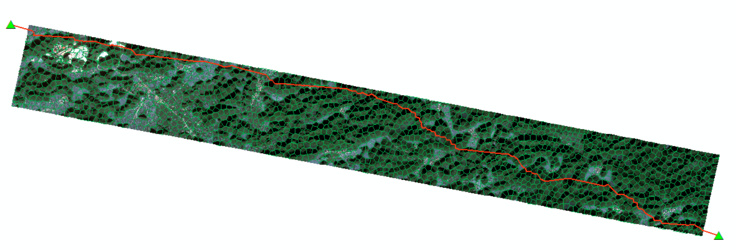
The mosaic line is actually the seam in the field of cv. When doing remote sensing image mosaic, in order to make the transition of the splicing natural, it is necessary for the line at the splicing to present a winding state. Some needs also require the mosaic line to avoid houses, take the terrain line and so on. Mosaic line algorithm, in ENVI the auto generate seamlines can be very intuitive to see the generation. However, the mosaic lines generated in ENVI are very straight, directly passing through some obvious curve textures, which makes the mosaic image leave obvious mosaic marks. The realization of this algorithm is mainly to solve the problem of straight splicing line.

Introduction to the algorithm

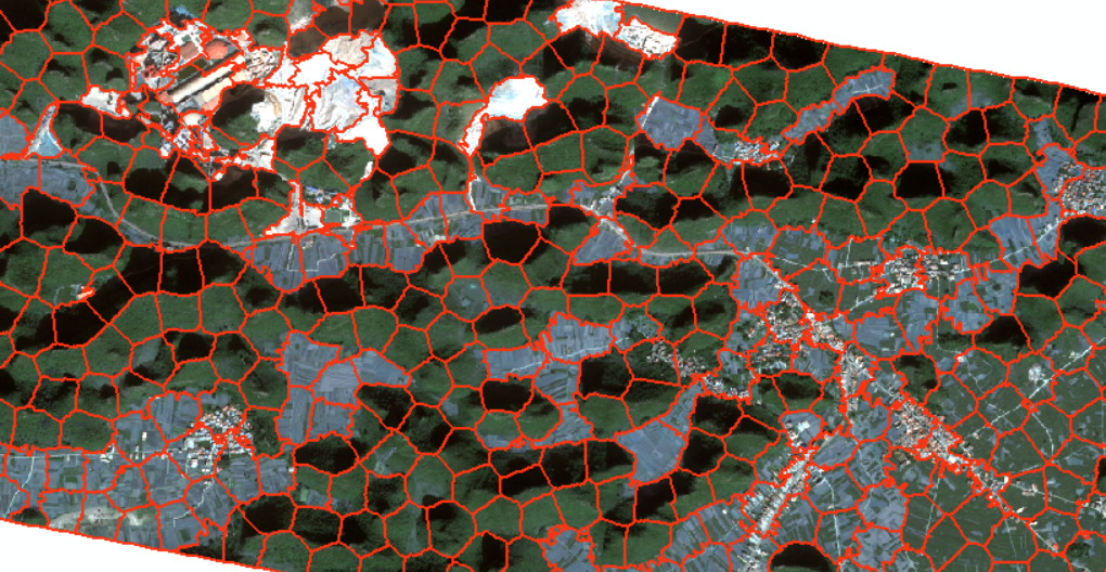
The main points mainly include several parts. Generally, mosaic is carried out after orthographic correction. After orthographic correction, the image will be rotated to a certain extent, and the black area generated is the area filled with 0 value. This part of the area does not need to be processed, so we need to extract the effective area when processing; The method of generating paths based on image texture features is mainly obtained by using the super-pixel segmentation method in the previous article; the general idea of mosaic line mosaic is to generate lines first, then cut out the irregular edges of a single image, and finally splice them according to the warp method given by gdal.

Introduction to packages used

whl name Version whl name version whl name version whl name version
os basic whl cv2 4.6.0.66 networkx 2.8.6 pathlib basic whl
math basic whl ogr 3.4.3 itertools basic whl geopandas 0.11.1
shapefile basic whl osr 3.4.3 shapely 2.3.1 skimage 0.19.3
tarfile basic whl gdal 3.4.3 shutil basic whl numpy 1.23.3
time basic whl gdalconst 3.4.3 topojson 1.5 python 3.10.4

Some of the names of the packages are not quite right, but most of them are correct, mainly scikit-image and networkx gdal and opencv. Some of the interesting points are that the shapely package needs to be written when it is installed

1
pip install pyshp

Full code

The code is very long, below according to the different function, take the main function as the mentality, carries on disassembles one by one.

Master function

 1
 2
 3
 4
 5
 6
 7
 8
 9
10
11
12
13
14
15
16
17
18
19
20
21
22
23
24
25
26
27
28
29
30
31
32
33
34
35
36
37
38
39
40
41
42
43
44
45
46
47
48
49
50
51
52
53
54
55
56
57
58
59
60
61
62
63
64
65
66
67
68
69
70
71
72
73
74
75
76
77
78
79
80
81
82
83
84
85
86

def main(input1, input2, output):
    time_start=time.time()
    print("start deal")
    tempdir = os.path.join(os.path.dirname(output),"temp")
    try:
        os.mkdir(tempdir)
    except Exception as e:
        pass


    # 过程文件
    out_raster1 = os.path.join(tempdir,"out_raster1.tif")
    out_raster2 = os.path.join(tempdir,"out_raster2.tif")
    outputfile1 = os.path.join(tempdir,"bina_shp1.shp")
    outputfile2 = os.path.join(tempdir,"bina_shp2.shp")
    outShp1 = os.path.join(tempdir,"select_shp1.shp")
    outShp2 = os.path.join(tempdir,"select_shp2.shp")
    outshp_intersect = os.path.join(tempdir,"intersect_shp.shp")
    inter_sim_shp = os.path.join(tempdir,"intersect_simply_shp.shp")
    output_raster = os.path.join(tempdir,"clip_interest_raster.tif")
    resample_raster = os.path.join(tempdir,"clip_resample_raster.tif")
    out_shp_point = os.path.join(tempdir,"start_end_point.shp")
    seg_raster = os.path.join(tempdir,"seg_raster.tif")
    seg_poly = os.path.join(tempdir,"seg_poly_shp.shp")
    seg_line = os.path.join(tempdir,"seg_line_shp.shp")
    seg_line_sim = os.path.join(tempdir,"seg_line_sim.shp")
    seg_line_mer_inter = os.path.join(tempdir,"seg_line_mer_inter_shp.shp")
    intersect_buffer = os.path.join(tempdir,"intersect_buffer.shp")
    seg_line_mer = os.path.join(tempdir,"seg_line_mer.shp")
    # simplify_seg_line = os.path.join(tempdir,"sim_seg_line.shp")
    shortestpath = os.path.join(tempdir,"shortestpath.shp")
    bufferline = os.path.join(tempdir,"cutline_buffer.shp")
    mosaic_mask_clip = os.path.join(tempdir,"mosaic_mask1.shp")
    mosaic_mask_true = os.path.join(tempdir,"mosaic_mask_true.shp")
    mask_temp = os.path.join(tempdir,"mask_temp.shp")
    mask_raster = os.path.join(tempdir,"mask_raster.tif")
    buffer_line = os.path.join(tempdir,"buffer_line.shp")
   
    
    # 函数开始处理部分
    raster_binary(input1,out_raster1)
    raster_binary(input2,out_raster2)

    PolygonizeTheRaster_bina(out_raster1,outputfile1)
    PolygonizeTheRaster_bina(out_raster2,outputfile2)
    print("Binarize done")
    SelectByAttribute(outputfile1, outShp1)
    SelectByAttribute(outputfile2, outShp2)

    get_intersect_shp(outShp1 , outShp2, outshp_intersect)
    simplifyshp(outshp_intersect, inter_sim_shp)
    print("Simplify done")
    clip_raster_from_intersect(input1, inter_sim_shp, output_raster)
    resample_for_seg(output_raster, resample_raster)
    start2 = time.time()
    print("Start segment")
    segementation_img(resample_raster, seg_raster)
    end2 = time.time()
    print('seg time cost',end2-start2,'s')
    print("Segment done")
    tolerance = PolygonizeTheRaster(seg_raster,seg_poly)
    pol2line(seg_poly, seg_line)
    topo_simplify(seg_line, seg_line_sim, tolerance)
    
    merge_all_feature_in_one(seg_line_sim,seg_line_mer)
    get_intersect_shp(seg_line_mer , outshp_intersect, seg_line_mer_inter)
    print("Polygonized done")
    buffer(outshp_intersect, intersect_buffer, -0.00005)
    get_intersect_shp(seg_line_mer_inter , intersect_buffer, buffer_line)


    get_start_end_points(inter_sim_shp, out_shp_point)
    print("start to find shortest path")
    shortest_path_dijsktra(buffer_line, out_shp_point, shortestpath)
    print("Find shortest path done")
    buffer(shortestpath, bufferline, 0.000000001)
    get_differ_shp(outShp1, bufferline, mosaic_mask_clip)
    explord(mosaic_mask_clip, mosaic_mask_true, mask_temp)
    RasterMosaic(input1, input2, mask_raster, output, mosaic_mask_true)
    print("Mosaic done")
    time_end=time.time()
    print('time cost',time_end-time_start,'s')
    #shutil.rmtree(tempdir) 
    buildpyramid(outputfile)

In order to facilitate debugging and checking, the process files are generated one by one here, but in fact, gdal has a corresponding memory method that virtul raster can directly put the array into memory, which will be rewritten as a memory method later when the project is close to completion.

Grid binarization

 1
 2
 3
 4
 5
 6
 7
 8
 9
10
11
12
def raster_binary(input_raster,out_raster):
    dataset = gdal.Open(input_raster)
    im_width = dataset.RasterXSize
    im_height = dataset.RasterYSize
    im_geotrans = dataset.GetGeoTransform()
    im_proj = dataset.GetProjection()
    im_data = dataset.ReadAsArray(0, 0, im_width, im_height)
    # re0 = im_data.transpose((2, 1, 0)) 
    ret, border0 = cv2.threshold(im_data[0], 0, 1, cv2.THRESH_BINARY)
    # border0 = border0.transpose((2, 1, 0)) 
    write_img(out_raster, im_proj, im_geotrans, border0) 
    del dataset

Here mainly aims at the multi-band grid, has carried on the binarization to extract the grid effective scope, uses is the cv package.

灰色区域的值 黑色区域的值

After binarization, only 0 and 1 are left in the grid to facilitate grid to vector assignment.

Binary grid to vector

 1
 2
 3
 4
 5
 6
 7
 8
 9
10
11
12
13
14
15
def PolygonizeTheRaster_bina(inputfile,outputfile):
    dataset = gdal.Open(inputfile, gdal.GA_ReadOnly)
    srcband=dataset.GetRasterBand(1)
    im_proj = dataset.GetProjection()
    prj = osr.SpatialReference() 
    prj.ImportFromWkt(im_proj)
    drv = ogr.GetDriverByName('ESRI Shapefile')
    dst_ds = drv.CreateDataSource(outputfile)
    dst_layername = 'out'
    dst_layer = dst_ds.CreateLayer(dst_layername, srs=prj)
    dst_fieldname = 'DN'
    fd = ogr.FieldDefn(dst_fieldname, ogr.OFTInteger)
    dst_layer.CreateField(fd)
    dst_field = 0
    gdal.Polygonize(srcband, None, dst_layer, dst_field) 

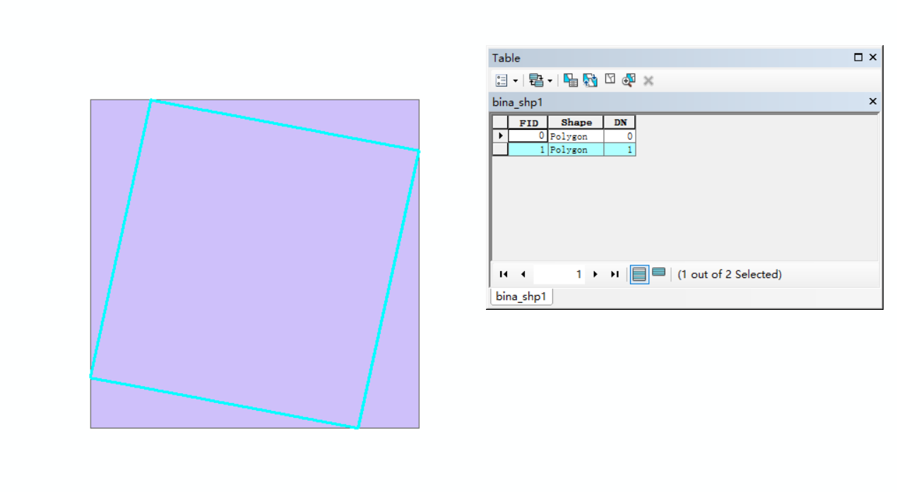
The binarization grid also mainly uses the osr library. Those who are familiar with gdal should know that gdal, OSR, ogr and other geographic data processing packages have been osgeo gradually incorporated into the management since a certain year, using the open source foundation to generate the power of sustainable development. The grid value of the previous binarization is used to polygon facilitate the subsequent extraction of the SHP block with a value of 1.

栅格转矢量

Select a polygon block based on the attribute values

 1
 2
 3
 4
 5
 6
 7
 8
 9
10
11
12
13
14
15
16
17

def SelectByAttribute(InShp, outShp):
    open_parks = ogr.Open(InShp)
    layer_park = open_parks.GetLayer(0)
    layer_park.SetAttributeFilter("DN = '1'")
    number_park = layer_park.GetFeatureCount()
    driver = ogr.GetDriverByName("ESRI shapefile")
    if os.path.exists(outShp):
        driver.DeleteDataSource(outShp)
    dataset = driver.CreateDataSource(outShp)
    spatialref_new = osr.SpatialReference()
    spatialref_new.ImportFromEPSG(4326)
    new_layer = dataset.CreateLayer(outShp, geom_type= ogr.wkbPolygon, srs=spatialref_new)
    for j in range(0, number_park):
        h = layer_park.GetNextFeature()
        new_layer.CreateFeature(h)
    dataset.Destroy()

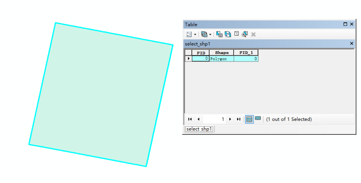
Based on the ogr package, the vector block with DN value equal to 1 is selected through the key function SetAttributeFilter, and a new SHP is created to be saved

Select a polygon block based on the attribute values

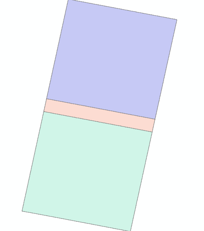
Find the processing area of the mosaic line

This is mainly to use the effective area SHP to find the intersection. After the above functions are used to process the two images to be inlaid, the intersection of the two images is obtained based on the geopandas package.

1
2
3
4
5
6
def get_intersect_shp(out_shp_ring1 , out_shp_ring2, outshp_intersect):
    gdf_left = gpd.read_file(out_shp_ring1)
    gdf_right = gpd.read_file(out_shp_ring2)
    gdf_intersect = gpd.overlay(gdf_left,gdf_right,'intersection',keep_geom_type=True)
    gdf_intersect.to_file(outshp_intersect)
    

Of course, after getting the intersection, part of the boundary of the vector is jagged, because the process of converting the grid to the vector does not simplify the jaggies. The reduced function is given here.

1
2
3
4
5
def simplifyshp(input, output): 
  
    gdf_main = gpd.read_file(input)            
    simp = gdf_main.simplify(tolerance=0.001, preserve_topology=True)
    simp.to_file(output)

求镶嵌线处理区域

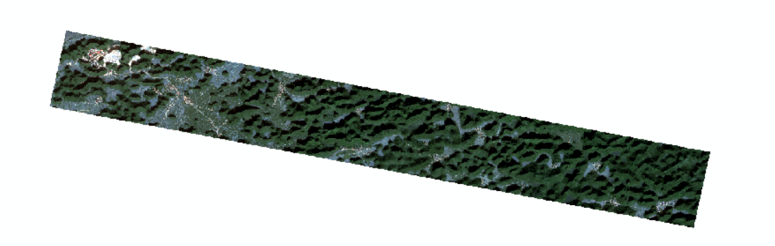
Clips the imported original grid with the valid area

1
2
3
4
5
6
7
8
9
def clip_raster_from_intersect(input_main_raster, input_shp, output_raster):
    input_raster=gdal.Open(input_main_raster)
    ds = gdal.Warp(output_raster,
                input_raster,
                format = 'GTiff',
                cutlineDSName = input_shp,    
                cutlineWhere="FIELD = 'whatever'",
                dstNodata = -9999)          
    ds=None  

This is mainly based on the warp function to clip the original grid, obtain the overlapping area of the two images and output it as TIF, which is convenient for the subsequent use of super-resolution segmentation.

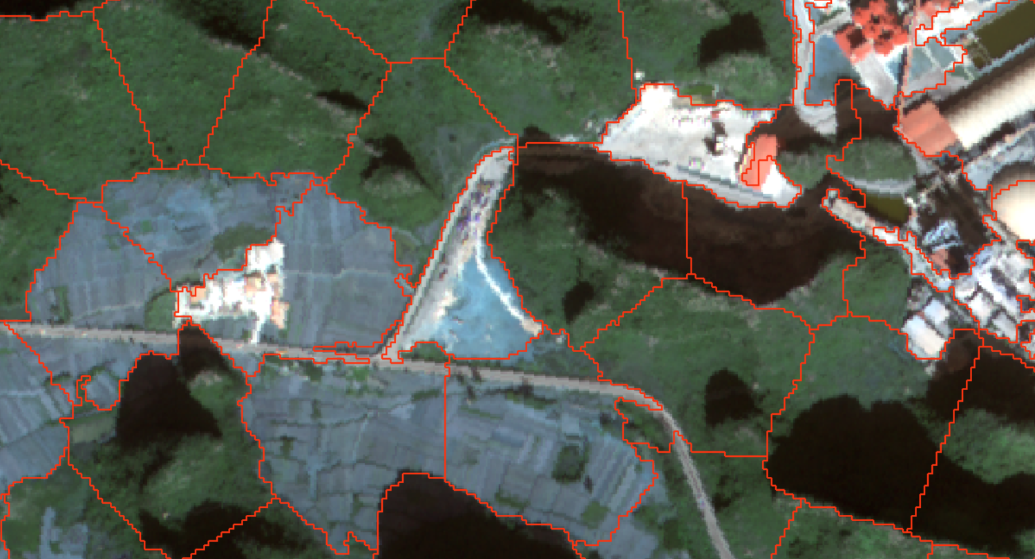
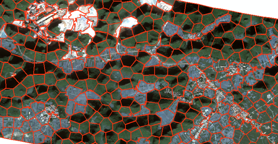
Superpixel segmentation

Because SLIC quickshift it takes a long time to process large-resolution images, I use downsampling to reduce the resolution of images, and then use low-resolution images to segment them. The test speed is increased from 500 seconds to 90 seconds. The resampling function is as follows:

1
2
3
4
5
6
def resample_for_seg(input_Dir, output_dir):
    dataset = gdal.Open(input_Dir, gdal.GA_ReadOnly)
    ds_trans = dataset.GetGeoTransform()
    res = ds_trans[1]*2
    gdal.Translate(output_dir, input_Dir, xRes=res, yRes=res, resampleAlg="bilinear", format="GTiff")
    

Then there is the main segmentation function.

 1
 2
 3
 4
 5
 6
 7
 8
 9
10
11
12
13
14
15
16
17
18
19
20
21
22
23
24
25
26

def segementation_img(input_raster, output_raster):
  
    dataset = gdal.Open(input_raster)
    im_width = dataset.RasterXSize
    im_height = dataset.RasterYSize
    im_geotrans = dataset.GetGeoTransform()
    im_proj = dataset.GetProjection()
    im_data = dataset.ReadAsArray(0, 0, im_width, im_height) #0, 0, im_width, im_height
    bandnum = dataset.RasterCount
    im_data = im_data.astype(int)
    if bandnum == 1:
        temp, mask_arra = im_data.transpose((1,0))
    
    elif bandnum == 2:
        im_data = im_data[0]
        temp, mask_arra = im_data.transpose((1,0))
    else:
        im_data = im_data[0:3]
        temp = im_data.transpose((2, 1, 0))
        mask_arra = temp[:, : , 0]
    mask = create_mask(mask_arra)
    seg_func = slic(temp, n_segments=2000, compactness=10, mask=mask)  #1
    #seg_func = quickshift(temp, ratio=1.0, kernel_size=5)
    label = seg_func.transpose((1,0))
    write_img(output_raster, im_proj, im_geotrans, label)

The SLIC segmentation algorithm is used here. The parameter settings are basically conventional, and there is not much attempt. The reason is that this is simply to obtain the network path. In fact, how complex it is is useless. If it is too square, it is not as good as Voronoi that, so it is set in the middle.

分割粗结果

Segmentation result processing

Convert the split grid to a vector line. Difficulties have been encountered here, because the gdal grid to vector can only be converted from the grid to the face, but not directly to the line, so it is necessary to convert the grid to the face first and then to the line:

 1
 2
 3
 4
 5
 6
 7
 8
 9
10
11
12
13
14
15
16
17
18
19
20
21
22
23
24
25
26
27
28
29
30
31
32
33
34
35
36
def PolygonizeTheRaster(inputfile,outputfile):
    dataset = gdal.Open(inputfile, gdal.GA_ReadOnly)
    srcband=dataset.GetRasterBand(1)
    im_proj = dataset.GetProjection()
    im_trans = dataset.GetGeoTransform()
    tolerance = im_trans[1]*5
    prj = osr.SpatialReference() 
    prj.ImportFromWkt(im_proj)
    drv = ogr.GetDriverByName('ESRI Shapefile')
    dst_ds = drv.CreateDataSource(outputfile)
    dst_layername = 'out'
    dst_layer = dst_ds.CreateLayer(dst_layername, srs=prj)
    dst_fieldname = 'DN'
    fd = ogr.FieldDefn(dst_fieldname, ogr.OFTInteger)
    dst_layer.CreateField(fd)
    dst_field = 0
    gdal.Polygonize(srcband, None, dst_layer, dst_field) 
    return tolerance

def pol2line(polyfn, linefn):
    driver = ogr.GetDriverByName('ESRI Shapefile')
    polyds = ogr.Open(polyfn, 0)
    polyLayer = polyds.GetLayer()
    spatialref = polyLayer.GetSpatialRef()
    if os.path.exists(linefn):
        driver.DeleteDataSource(linefn)
    lineds =driver.CreateDataSource(linefn)
    linelayer = lineds.CreateLayer(linefn, srs=spatialref, geom_type=ogr.wkbLineString)
    featuredefn = linelayer.GetLayerDefn()
    for feat in polyLayer:
        geom = feat.GetGeometryRef()
        ring = geom.GetGeometryRef(0)
        outfeature = ogr.Feature(featuredefn)
        outfeature.SetGeometry(ring)
        linelayer.CreateFeature(outfeature)
        outfeature = None

The code is also a conventional way of writing, each step of the operation will be output to a file to facilitate the inspection and analysis of the problem. After the segmentation result line is output, a simplification is performed to remove the sawtooth problem of the gdal raster to vector. A new method is used here to simplify the function:

1
2
3
4
5
def topo_simplify(input, output, tolerance):
    gdf = gpd.read_file(input)
    topo = tp.Topology(gdf, prequantize=False)
    gdf = topo.toposimplify(tolerance).to_gdf()
    gdf.to_file(output, driver="ESRI Shapefile")

简化未简化

As a result of the vector line after division, each block is a separate object, and we need to merge all objects into one object:

1
2
3
4
5
6
7
def merge_all_feature_in_one(input, output):
    gdf = gpd.read_file(input)
    geom = gdf['geometry']
    new_geom = gpd.tools.collect(geom)
    df = {'id': [0], 'geometry': [new_geom]}
    new_gdf = gpd.GeoDataFrame(df, crs="EPSG:4326")
    new_gdf.to_file(output)

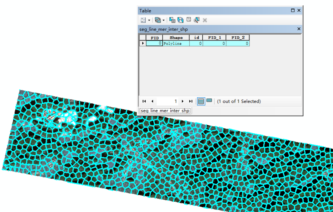
The test found that there are still some inexplicable scattered lines in the result of merging, and sometimes there are various problems, so in order to be on the safe side, reverse thinking here is to intersect the dividing line with the dividing area to get the overall line layer, which contains only one object:

1
2
3
4
5
def get_intersect_shp(out_shp_ring1 , out_shp_ring2, outshp_intersect):
    gdf_left = gpd.read_file(out_shp_ring1)
    gdf_right = gpd.read_file(out_shp_ring2)
    gdf_intersect = gpd.overlay(gdf_left,gdf_right,'intersection',keep_geom_type=True)
    gdf_intersect.to_file(outshp_intersect)

Gets the start and end points of the tessellation line

The idea here is to take the diagonal points of the SHP blocks in the grid intersection area as the starting and ending points, and use vector packages such as geopandas to easily obtain the corner coordinates:
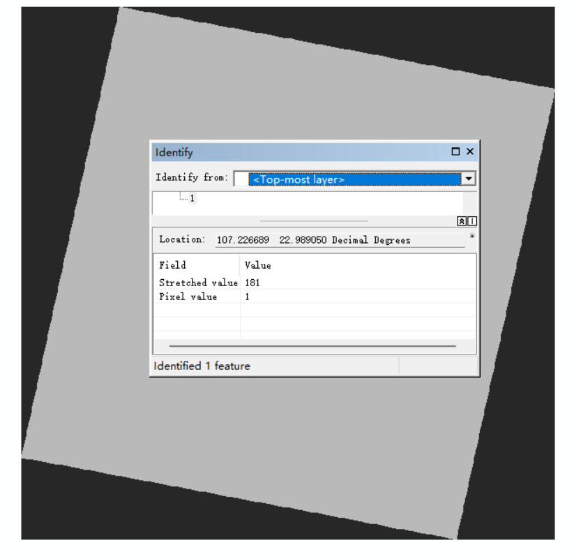
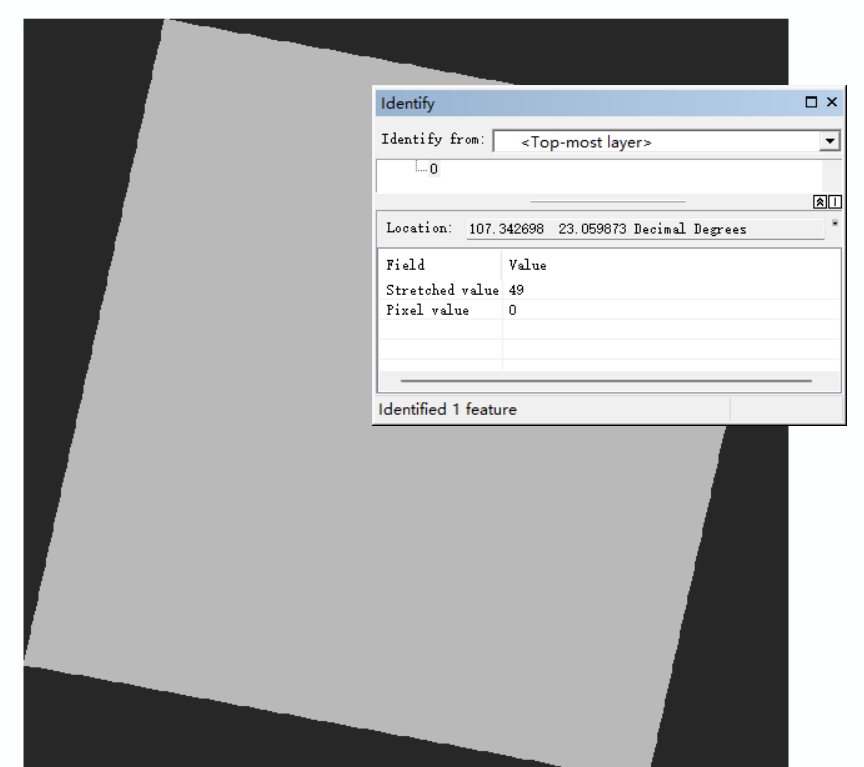
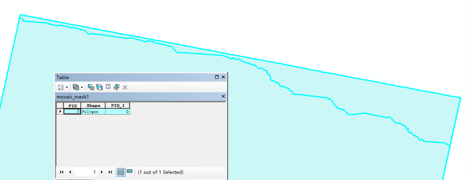
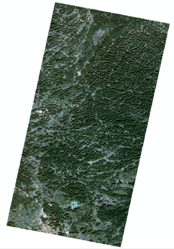
 1
 2
 3
 4
 5
 6
 7
 8
 9
10
11
12
13
14
15
16
17
18
19
20
21
22
23
24
25


def get_start_end_points(intersect_shp, out_shp_point):
    inDriver = ogr.GetDriverByName("ESRI Shapefile")
    inDataSource = inDriver.Open(intersect_shp, 0)
    inLayer = inDataSource.GetLayer()
    extent = inLayer.GetExtent()
    elon = abs( extent[0] - extent[1] )
    elat = abs( extent[2] - extent[3] )

    if elat> elon:
        start = geometry.Point(extent[0],extent[2])
        end = geometry.Point(extent[1], extent[3])
    else:
        start = geometry.Point(extent[1], extent[2])
        end = geometry.Point(extent[0], extent[3])
        
    pointshp = gpd.GeoSeries([start, end],               
                                crs='EPSG:4326', 
                                index=['0', '1']
                                )
    pointshp.to_file(out_shp_point,driver='ESRI Shapefile',encoding='utf-8')
    inDataSource = None
    out_shp_point = None
    

Some people 起点终点 
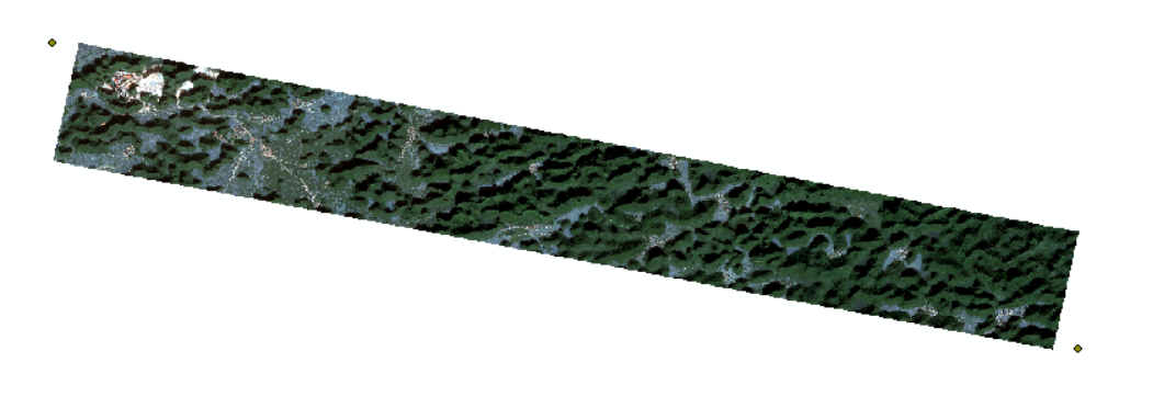
here may ask why the corner is not at the edge of the image. In fact, the overall range of the image is like this: 
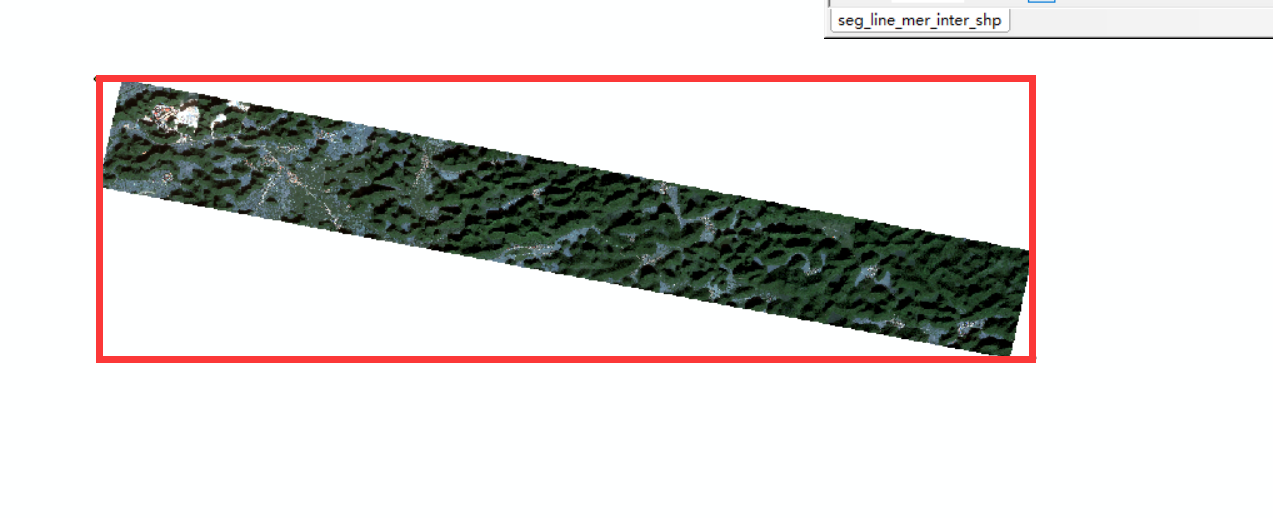
only because of the setting of arcmap’s ignore background value, the background of the image display is ignored.

Optimal Path Algorithm

In the article posted some time ago, there is actually an introduction to this, which is mainly based on the networkx package. There are astar three options for the algorithm, dijkstra, and bellman-ford. Here is a star:

 1
 2
 3
 4
 5
 6
 7
 8
 9
10
11
12
13
14
15
16
17
18
19
20
21
22
23
24
25
26
27
28
29
30
31
32
33
34
35
36
37
38
39
40
41
42
43
44
45
46
47
48
49
50
51
52
53
54
55
56
57
58
59
60
61
62

def shortest_path_dijsktra(input_road_shp, input_point_shp, outpath):
    driver = ogr.GetDriverByName('ESRI Shapefile')
    G = nx.DiGraph()
    r1 = shapefile.Reader(input_road_shp)
    for s in r1.shapes():
        for p1, p2 in pairwise(s.points):
            G.add_edge(tuple(p1), tuple(p2))
    sg = list(G.to_undirected(c) for c in nx.strongly_connected_components(G))[0]
    r2 = shapefile.Reader(input_point_shp)
    start = r2.shape(0).points[0]
    end = r2.shape(1).points[0]
    for n0, n1 in sg.edges():
        dist = haversine(n0, n1)
        sg.edges[n0,n1]["dist"] = dist

    nn_start = None
    nn_end = None
    start_delta = float("inf")
    end_delta = float("inf")
    for n in sg.nodes():
        s_dist = haversine(start, n)
        e_dist = haversine(end, n)
        if s_dist < start_delta:
            nn_start = n
            start_delta = s_dist
        if e_dist < end_delta:
            nn_end = n
            end_delta = e_dist
        nx.shortest_path
    path = nx.astar_path(sg, source=nn_start, target=nn_end, weight="dist") #list , method="bellman-ford"
    multiline = ogr.Geometry(ogr.wkbMultiLineString)
    line = ogr.Geometry(ogr.wkbLineString)
    print(start[0], start[1])
    line.AddPoint(start[0], start[1])
    for point in path:
        print(point[0], point[1])
        line.AddPoint(point[0],point[1])  #  添加点01
    print(end[0])
    print(end[1])
    line.AddPoint(end[0], end[1])

    multiline.AddGeometry(line)
    wkt = multiline.ExportToWkt()
    driver = ogr.GetDriverByName("ESRI Shapefile")
    data_source = driver.CreateDataSource(outpath)
    srs = osr.SpatialReference()
    srs.ImportFromEPSG(4326)
    layer = data_source.CreateLayer("path", srs, ogr.wkbLineString )
    field_name = ogr.FieldDefn("Name", ogr.OFTString)
    field_name.SetWidth(14)
    layer.CreateField(field_name)
    field_name = ogr.FieldDefn("data", ogr.OFTString)
    field_name.SetWidth(14)
    layer.CreateField(field_name)
    feature = ogr.Feature(layer.GetLayerDefn())
    feature.SetField("Name", "path")
    line = ogr.CreateGeometryFromWkt(wkt)
    feature.SetGeometry(line)
    layer.CreateFeature(feature)
    feature = None
    data_source = None

最优路径结果

Vector line clipping face

Unexpectedly, this is still very difficult. At present, there should be very few bloggers to write this introduction. Here is a brief introduction of ideas. The purpose is to use the generated optimal path polyline to clip the range polygon of the grid. First, the line is used as a buffer, and the buffer value needs to be very small. Then, the generated buffer polygon surface grid range SHP, which is almost a line, is used to calculate the difference, and the split SHP can be obtained:

 1
 2
 3
 4
 5
 6
 7
 8
 9
10
11
12
13
14
15
16
17
18
19
20
21
22
23
24
25
26
27
28
29
30
31
 
def buffer(inShp, out, value):
    """
    :param inShp: 输入的矢量路径
    :param fname: 输出的矢量路径
    :param bdistance: 缓冲区距离
    :return:
    """
    ogr.UseExceptions()
    in_ds = ogr.Open(inShp)
    in_lyr = in_ds.GetLayer()
    driver = ogr.GetDriverByName('ESRI Shapefile')
    if Path(out).exists():
        driver.DeleteDataSource(out)
    out_ds = driver.CreateDataSource(out)
    out_lyr = out_ds.CreateLayer(out, in_lyr.GetSpatialRef(), ogr.wkbPolygon)
    def_feature = out_lyr.GetLayerDefn()
    for feature in in_lyr:
        geometry = feature.GetGeometryRef()
        buffer = geometry.Buffer(value)
        out_feature = ogr.Feature(def_feature)
        out_feature.SetGeometry(buffer)
        out_lyr.CreateFeature(out_feature)
        out_feature = None

def get_differ_shp(input_main,input_minor,output_differ):
    gdf_main = gpd.read_file(input_main)
    gdf_minor = gpd.read_file(input_minor)
    gdf_differ= gpd.overlay(gdf_main,gdf_minor,'difference')
    gdf_differ.to_file(output_differ)
    

Although the correlation function is also written in the previous text, the number of water words is given here.

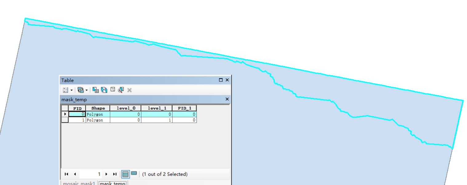
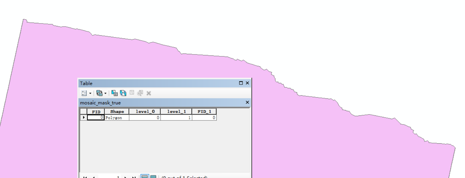
After processing the above content, in fact, the two faces to be split are still in the same object. We need to “explode” the integrated object, then sort it according to the size of the area, and select the area with the largest area to output, so that we can get the real mosaic line clipping area of the grid.

 1
 2
 3
 4
 5
 6
 7
 8
 9
10
def explord(input,output , output_temp):
    gdf_main = gpd.read_file(input)
    explord = gpd.GeoDataFrame.explode(gdf_main)
    explord.to_file(output_temp, driver="ESRI Shapefile")

    output_temp_shp = gpd.read_file(output_temp)
    areas = output_temp_shp.area
    index = areas.sort_values(ascending = False).index.tolist()[0]
    row = output_temp_shp.loc[[index]]
    row.to_file(output, driver="ESRI Shapefile")

Inlay

The result of the clipping of the tessellation line is obtained, and then the formal tessellation is performed:

 1
 2
 3
 4
 5
 6
 7
 8
 9
10
11
12
13
14
15
16
17
18
19
20
21
22
23

def RasterMosaic(inputfilePath, referencefilefilePath, outputfile, outputfile2, cutline):
  
    inputrasfile1 = gdal.Open(inputfilePath, gdal.GA_ReadOnly) # 第一幅影像
    inputProj1 = inputrasfile1.GetProjection()
    inputrasfile2 = gdal.Open(referencefilefilePath, gdal.GA_ReadOnly) # 第二幅影像
    options=gdal.WarpOptions(srcSRS=inputProj1, 
                             dstSRS=inputProj1,
                             format='GTiff', 
                            resampleAlg=gdalconst.GRA_Bilinear,
                            srcNodata=0, 
                            dstNodata=0, 
                            cutlineDSName=cutline
                            )
    options2=gdal.WarpOptions(srcSRS=inputProj1, 
                            dstSRS=inputProj1,
                            format='GTiff', 
                            resampleAlg=gdalconst.GRA_Bilinear,
                            srcNodata=0, 
                            dstNodata=0
                            )
    gdal.Warp(outputfile,inputrasfile1,options=options)
    gdal.Warp(outputfile2, [inputrasfile2,outputfile], options=options2)

Here I also studied, it seems that gdal can not directly write the option in a warp in one step, and then cut the direct mosaic, can only be done step by step, basically is the warp function, gdal is really powerful.

Here, due to the better quality of the two images, there is no clear dividing line.

Post-processing work

Mainly refers to the work of the pyramid, because it is the final work, so the previous generation process did not build the pyramid, I only build the pyramid in the mosaic image, mainly for the convenience of viewing, this code is not difficult.

1
2
3
4
5
6

def buildpyramid(input):
    Image = gdal.Open(input, 0)  # 0 = read-only, 1 = read-write.
    gdal.SetConfigOption('COMPRESS_OVERVIEW', 'DEFLATE')
    Image.BuildOverviews('NEAREST', [4, 8, 16, 32, 64, 128], gdal.TermProgress_nocb)
    del Image  # close the dataset (Python object and pointers)

Sum up

This idea is also running-in for a long time. At the beginning, I thought about using cv seamless stitch, but I found that it would destroy the real value of the image. I could only use physical methods to generate mosaic lines. The task requirement is to avoid the house. There is no idea here. What I thought before was to use the mask function of super-pixel segmentation to make a mask for the house area. Based on the NDVI and OTSU threshold method, the building area is extracted as the non-selected area for segmentation, but it is found that the optimal path will still follow all areas, but based on arcmap, it can normally follow the non-building area. The reason may be that the underlying algorithm of ArcGIS is different from that of gdal, but I don’t have much ability and energy to study the underlying problems, so I can only divide them according to the architectural texture as much as possible at present.

The main code is to change the file output of vector and raster. It is time-consuming to read and write all the time. In practical application, it should be rewritten as a virtual dataset unified processing package for vector. However, there is also a problem involved here, such as how to operate the vectorization of virtual raster, such as the conversion of raster to surface. Existing packages are generated based on local raster files. If they are placed in a virtual raster, will they be stored in an array? This is an unknown problem that needs to be verified.

Although geopandas is powerful, there are too many dependent packages, including Fiona, but in fact, Fiona and other packages can also implement all the above algorithms about vectors. It remains to be verified whether the vector technology stack can be replaced by ogr or Fiona.

The generation network path mentioned voronoi above is actually an alternative to SLIC, because the generation speed of Voronoi diagram is theoretically far superior to SLIC or quickshift, but the triangulation generated by Voronoi diagram is too square, which will lead to the loss of some texture routes. If we add the manual editing of mosaic lines in the later stage, that is, the semi-automatic generation of mosaic lines, in fact, the idea of Voronoi diagram should be desirable. I have not studied the generation of Voronoi diagram due to time constraints, and we need to discuss and understand it in the future.

Appendix · General Code

  1
  2
  3
  4
  5
  6
  7
  8
  9
 10
 11
 12
 13
 14
 15
 16
 17
 18
 19
 20
 21
 22
 23
 24
 25
 26
 27
 28
 29
 30
 31
 32
 33
 34
 35
 36
 37
 38
 39
 40
 41
 42
 43
 44
 45
 46
 47
 48
 49
 50
 51
 52
 53
 54
 55
 56
 57
 58
 59
 60
 61
 62
 63
 64
 65
 66
 67
 68
 69
 70
 71
 72
 73
 74
 75
 76
 77
 78
 79
 80
 81
 82
 83
 84
 85
 86
 87
 88
 89
 90
 91
 92
 93
 94
 95
 96
 97
 98
 99
100
101
102
103
104
105
106
107
108
109
110
111
112
113
114
115
116
117
118
119
120
121
122
123
124
125
126
127
128
129
130
131
132
133
134
135
136
137
138
139
140
141
142
143
144
145
146
147
148
149
150
151
152
153
154
155
156
157
158
159
160
161
162
163
164
165
166
167
168
169
170
171
172
173
174
175
176
177
178
179
180
181
182
183
184
185
186
187
188
189
190
191
192
193
194
195
196
197
198
199
200
201
202
203
204
205
206
207
208
209
210
211
212
213
214
215
216
217
218
219
220
221
222
223
224
225
226
227
228
229
230
231
232
233
234
235
236
237
238
239
240
241
242
243
244
245
246
247
248
249
250
251
252
253
254
255
256
257
258
259
260
261
262
263
264
265
266
267
268
269
270
271
272
273
274
275
276
277
278
279
280
281
282
283
284
285
286
287
288
289
290
291
292
293
294
295
296
297
298
299
300
301
302
303
304
305
306
307
308
309
310
311
312
313
314
315
316
317
318
319
320
321
322
323
324
325
326
327
328
329
330
331
332
333
334
335
336
337
338
339
340
341
342
343
344
345
346
347
348
349
350
351
352
353
354
355
356
357
358
359
360
361
362
363
364
365
366
367
368
369
370
371
372
373
374
375
376
377
378
379
380
381
382
383
384
385
386
387
388
389
390
391
392
393
394
395
396
397
398
399
400
401
402
403
404
405
406
407
408
409
410
411
412
413
414
415
416
417
418
419
420
421
422
423
424
425
426
427
428
429
430
431
432
433
434
435
436
437
438
439
440
441
442
443
444
445
446
447
448
449
450
451
452
453
454
455
456
457
458
459
460
461
462
463
464
465
466
467
468
469
470
471
472
473
474
475
476
477
478
479
480
481
482
483
484
485
486
487
488
489
490
491
492
493
494
495
496
497
498
499
500
501
502
503
504
505
506
507
508
509
510
511
512
513
514
515
516
517
518
519
520
521
522
523
524
525
526
527
528
529
530
531
532
533
534
535
536
537
538
539
540
541
542
543
544
545
546
547
548
549
550
551
552
553
554
555
556
557
558
559
560
561
562
563
564
565
566
567
568
569
570
571
572
573
574
575
576
577
578
579
580
581
582
583
584
585
586
587
588
589
590
591
592
593
594
595
596
597
598
599
600
601
602
import os
import math
import shapefile
import tarfile
import time, shutil
from shapely import geometry
from itertools import tee
import networkx as nx
import cv2
from osgeo import ogr, osr, gdal, gdalconst
import numpy as np
from skimage.segmentation import slic
from skimage import morphology
import geopandas as gpd
from pathlib import Path
import topojson as tp


def create_mask(input_arra):
    mask = morphology.remove_small_holes(morphology.remove_small_objects(input_arra > 0, 500),500)
    mask = morphology.opening(mask, morphology.disk(3))
    return mask


def untar(fname, dirs):
    ''' 解压缩tar文件函数 '''
    t = tarfile.open(fname)
    t.extractall(path=dirs)

def write_img(filename, im_proj, im_geotrans, im_data):
    if 'int8' in im_data.dtype.name:
        datatype = gdal.GDT_Byte
    elif 'int16' in im_data.dtype.name:
        datatype = gdal.GDT_UInt16
    else:
        datatype = gdal.GDT_Float32

    if len(im_data.shape) >= 3:
        im_height  , im_width, im_bands = im_data.shape
    else:
        im_height, im_width = im_data.shape
        im_bands = 1
    driver = gdal.GetDriverByName("GTiff")
    dataset = driver.Create(filename, im_width, im_height, im_bands, datatype)

    dataset.SetGeoTransform(im_geotrans)
    dataset.SetProjection(im_proj)
    if im_bands == 1:
        dataset.GetRasterBand(1).WriteArray(im_data)
    else:
        for i in range(im_bands):
            dataset.GetRasterBand(i + 1).WriteArray(im_data[i+1])

    del dataset
    

def merge_mean_color(graph, src, dst):
    graph.nodes[dst]['total color'] += graph.nodes[src]['total color']
    graph.nodes[dst]['pixel count'] += graph.nodes[src]['pixel count']
    graph.nodes[dst]['mean color'] = (graph.nodes[dst]['total color'] /
                                    graph.nodes[dst]['pixel count'])


def segementation_img(input_raster, output_raster):
  
    dataset = gdal.Open(input_raster)
    im_width = dataset.RasterXSize
    im_height = dataset.RasterYSize
    im_geotrans = dataset.GetGeoTransform()
    im_proj = dataset.GetProjection()
    im_data = dataset.ReadAsArray(0, 0, im_width, im_height) #0, 0, im_width, im_height
    bandnum = dataset.RasterCount
    im_data = im_data.astype(int)
    if bandnum == 1:
        temp, mask_arra = im_data.transpose((1,0))
    
    elif bandnum == 2:
        im_data = im_data[0]
        temp, mask_arra = im_data.transpose((1,0))
    else:
        im_data = im_data[0:3]
        temp = im_data.transpose((2, 1, 0))
        mask_arra = temp[:, : , 0]
    mask = create_mask(mask_arra)
    seg_func = slic(temp, n_segments=2000, compactness=10, mask=mask)  #1
    #seg_func = quickshift(temp, ratio=1.0, kernel_size=5)
    label = seg_func.transpose((1,0))
    write_img(output_raster, im_proj, im_geotrans, label)

def PolygonizeTheRaster_bina(inputfile,outputfile):
    dataset = gdal.Open(inputfile, gdal.GA_ReadOnly)
    srcband=dataset.GetRasterBand(1)
    im_proj = dataset.GetProjection()
    prj = osr.SpatialReference() 
    prj.ImportFromWkt(im_proj)
    drv = ogr.GetDriverByName('ESRI Shapefile')
    dst_ds = drv.CreateDataSource(outputfile)
    dst_layername = 'out'
    dst_layer = dst_ds.CreateLayer(dst_layername, srs=prj)
    dst_fieldname = 'DN'
    fd = ogr.FieldDefn(dst_fieldname, ogr.OFTInteger)
    dst_layer.CreateField(fd)
    dst_field = 0
    gdal.Polygonize(srcband, None, dst_layer, dst_field) 
    
    
def SelectByAttribute(InShp, outShp):
    open_parks = ogr.Open(InShp)
    layer_park = open_parks.GetLayer(0)
    layer_park.SetAttributeFilter("DN = '1'")
    number_park = layer_park.GetFeatureCount()
    driver = ogr.GetDriverByName("ESRI shapefile")
    if os.path.exists(outShp):
        driver.DeleteDataSource(outShp)
    dataset = driver.CreateDataSource(outShp)
    spatialref_new = osr.SpatialReference()
    spatialref_new.ImportFromEPSG(4326)
    new_layer = dataset.CreateLayer(outShp, geom_type= ogr.wkbPolygon, srs=spatialref_new)
    for j in range(0, number_park):
        h = layer_park.GetNextFeature()
        new_layer.CreateFeature(h)
    dataset.Destroy()


def raster_binary(input_raster,out_raster):
    dataset = gdal.Open(input_raster)
    im_width = dataset.RasterXSize
    im_height = dataset.RasterYSize
    im_geotrans = dataset.GetGeoTransform()
    im_proj = dataset.GetProjection()
    im_data = dataset.ReadAsArray(0, 0, im_width, im_height)
    # re0 = im_data.transpose((2, 1, 0)) 
    ret, border0 = cv2.threshold(im_data[0], 0, 1, cv2.THRESH_BINARY)
    # border0 = border0.transpose((2, 1, 0)) 
    
    
    write_img(out_raster, im_proj, im_geotrans, border0) 
    del dataset
    

def PolygonizeTheRaster(inputfile,outputfile):
    dataset = gdal.Open(inputfile, gdal.GA_ReadOnly)
    srcband=dataset.GetRasterBand(1)
    im_proj = dataset.GetProjection()
    im_trans = dataset.GetGeoTransform()
    tolerance = im_trans[1]*5
    prj = osr.SpatialReference() 
    prj.ImportFromWkt(im_proj)
    drv = ogr.GetDriverByName('ESRI Shapefile')
    dst_ds = drv.CreateDataSource(outputfile)
    dst_layername = 'out'
    dst_layer = dst_ds.CreateLayer(dst_layername, srs=prj)
    dst_fieldname = 'DN'
    fd = ogr.FieldDefn(dst_fieldname, ogr.OFTInteger)
    dst_layer.CreateField(fd)
    dst_field = 0
    gdal.Polygonize(srcband, None, dst_layer, dst_field) 
    return tolerance
    

def pol2line(polyfn, linefn):
    """
        This function is used to make polygon convert to line
    :param polyfn: the path of input, the shapefile of polygon
    :param linefn: the path of output, the shapefile of line
    :return:
    """
    driver = ogr.GetDriverByName('ESRI Shapefile')
    polyds = ogr.Open(polyfn, 0)
    polyLayer = polyds.GetLayer()
    spatialref = polyLayer.GetSpatialRef()
    if os.path.exists(linefn):
        driver.DeleteDataSource(linefn)
    lineds =driver.CreateDataSource(linefn)
    linelayer = lineds.CreateLayer(linefn, srs=spatialref, geom_type=ogr.wkbLineString)
    featuredefn = linelayer.GetLayerDefn()
    for feat in polyLayer:
        geom = feat.GetGeometryRef()
        ring = geom.GetGeometryRef(0)
        outfeature = ogr.Feature(featuredefn)
        outfeature.SetGeometry(ring)
        linelayer.CreateFeature(outfeature)
        outfeature = None


def waibao(inShapefile, outShapefile):
    inDriver = ogr.GetDriverByName("ESRI Shapefile")
    inDataSource = inDriver.Open(inShapefile, 0)
    inLayer = inDataSource.GetLayer()
    geomcol = ogr.Geometry(ogr.wkbGeometryCollection) 
    for feature in inLayer:
        geomcol.AddGeometry(feature.GetGeometryRef())
    convexhull = geomcol.ConvexHull()
    outDriver = ogr.GetDriverByName("ESRI Shapefile")
    if os.path.exists(outShapefile):
        outDriver.DeleteDataSource(outShapefile)
    outDataSource = outDriver.CreateDataSource(outShapefile)
    outLayer = outDataSource.CreateLayer("test_convexhull", geom_type=ogr.wkbPolygon)
    idField = ogr.FieldDefn("id", ogr.OFTInteger)
    outLayer.CreateField(idField)
    featureDefn = outLayer.GetLayerDefn()
    feature = ogr.Feature(featureDefn)
    feature.SetGeometry(convexhull)
    feature.SetField("id", 1)
    outLayer.CreateFeature(feature)
    feature = None
    inDataSource = None
    outDataSource = None


def get_differ_shp(input_main,input_minor,output_differ):
    gdf_main = gpd.read_file(input_main)
    gdf_minor = gpd.read_file(input_minor)
    gdf_differ= gpd.overlay(gdf_main,gdf_minor,'difference')
    gdf_differ.to_file(output_differ)


def get_intersect_shp(out_shp_ring1 , out_shp_ring2, outshp_intersect):
    gdf_left = gpd.read_file(out_shp_ring1)
    gdf_right = gpd.read_file(out_shp_ring2)
    gdf_intersect = gpd.overlay(gdf_left,gdf_right,'intersection',keep_geom_type=True)
    gdf_intersect.to_file(outshp_intersect)


def clip_raster_from_intersect(input_main_raster, input_shp, output_raster):
    input_raster=gdal.Open(input_main_raster)
    ds = gdal.Warp(output_raster,
                input_raster,
                format = 'GTiff',
                cutlineDSName = input_shp,    
                cutlineWhere="FIELD = 'whatever'",
                dstNodata = -9999)          
    ds=None           


def get_start_end_points(intersect_shp, out_shp_point):
    inDriver = ogr.GetDriverByName("ESRI Shapefile")
    inDataSource = inDriver.Open(intersect_shp, 0)
    inLayer = inDataSource.GetLayer()
    extent = inLayer.GetExtent()
    elon = abs( extent[0] - extent[1] )
    elat = abs( extent[2] - extent[3] )

    if elat> elon:
        start = geometry.Point(extent[0],extent[2])
        end = geometry.Point(extent[1], extent[3])
    else:
        start = geometry.Point(extent[1], extent[2])
        end = geometry.Point(extent[0], extent[3])
        
    pointshp = gpd.GeoSeries([start, end],               
                                crs='EPSG:4326', 
                                index=['0', '1']
                                )
    pointshp.to_file(out_shp_point,driver='ESRI Shapefile',encoding='utf-8')
    inDataSource = None
    out_shp_point = None
    
    
def BetterMedianFilter(src_arr, k = 3, padding = None):
    height, width = src_arr.shape

    if not padding:
        edge = int((k-1)/2)
        if height - 1 - edge <= edge or width - 1 - edge <= edge:
            print("The parameter k is to large.")
            return None
        new_arr = np.zeros((height, width), dtype = "uint16")
        for i in range(height):
            for j in range(width):
                if i <= edge - 1 or i >= height - 1 - edge or j <= edge - 1 or j >= height - edge - 1:
                    new_arr[i, j] = src_arr[i, j]
                else:
                    nm = src_arr[i - edge:i + edge + 1, j - edge:j + edge + 1]
                    max = np.max(nm)
                    min = np.min(nm)
                    if src_arr[i, j] == max or src_arr[i, j] == min:
                        new_arr[i, j] = np.median(nm)
                    else:
                        new_arr[i, j] = src_arr[i, j]
        return new_arr


def haversine(n0, n1):
    x1, y1 = n0
    x2, y2 = n1
    x_dist = math.radians(x1 - x2)
    y_dist = math.radians(y1 - y2)
    y1_rad = math.radians(y1)
    y2_rad = math.radians(y2)
    a = math.sin(y_dist/2)**2 + math.sin(x_dist/2)**2 \
    * math.cos(y1_rad) * math.cos(y2_rad)
    c = 2 * math.asin(math.sqrt(a))
    distance = c * 6371
    return distance

def pairwise(iterable):
    """返回可迭代访问的二值元组
s -> (s0,s1), (s1,s2), (s2, s3), ..."""
    a, b = tee(iterable)
    next(b, None)
    return zip(a, b)

def shortest_path_dijsktra(input_road_shp, input_point_shp, outpath):
    driver = ogr.GetDriverByName('ESRI Shapefile')
    G = nx.DiGraph()
    r1 = shapefile.Reader(input_road_shp)
    for s in r1.shapes():
        for p1, p2 in pairwise(s.points):
            G.add_edge(tuple(p1), tuple(p2))
    sg = list(G.to_undirected(c) for c in nx.strongly_connected_components(G))[0]
    r2 = shapefile.Reader(input_point_shp)
    start = r2.shape(0).points[0]
    end = r2.shape(1).points[0]
    for n0, n1 in sg.edges():
        dist = haversine(n0, n1)
        sg.edges[n0,n1]["dist"] = dist

    nn_start = None
    nn_end = None
    start_delta = float("inf")
    end_delta = float("inf")
    for n in sg.nodes():
        s_dist = haversine(start, n)
        e_dist = haversine(end, n)
        if s_dist < start_delta:
            nn_start = n
            start_delta = s_dist
        if e_dist < end_delta:
            nn_end = n
            end_delta = e_dist
        nx.shortest_path
    path = nx.astar_path(sg, source=nn_start, target=nn_end, weight="dist") #list , method="bellman-ford"
    multiline = ogr.Geometry(ogr.wkbMultiLineString)
    line = ogr.Geometry(ogr.wkbLineString)
    print(start[0], start[1])
    line.AddPoint(start[0], start[1])
    for point in path:
        print(point[0], point[1])
        line.AddPoint(point[0],point[1])  #  添加点01
    print(end[0])
    print(end[1])
    line.AddPoint(end[0], end[1])

    multiline.AddGeometry(line)
    wkt = multiline.ExportToWkt()
    driver = ogr.GetDriverByName("ESRI Shapefile")
    data_source = driver.CreateDataSource(outpath)
    srs = osr.SpatialReference()
    srs.ImportFromEPSG(4326)
    layer = data_source.CreateLayer("path", srs, ogr.wkbLineString )
    field_name = ogr.FieldDefn("Name", ogr.OFTString)
    field_name.SetWidth(14)
    layer.CreateField(field_name)
    field_name = ogr.FieldDefn("data", ogr.OFTString)
    field_name.SetWidth(14)
    layer.CreateField(field_name)
    feature = ogr.Feature(layer.GetLayerDefn())
    feature.SetField("Name", "path")
    line = ogr.CreateGeometryFromWkt(wkt)
    feature.SetGeometry(line)
    layer.CreateFeature(feature)
    feature = None
    data_source = None

def simplifyshp(input, output): #容差是分辨率的根号二倍
  
    gdf_main = gpd.read_file(input)            
    simp = gdf_main.simplify(tolerance=0.001, preserve_topology=True)
    simp.to_file(output)


def merge_all_feature_in_one(input, output):
    gdf = gpd.read_file(input)
    geom = gdf['geometry']
    new_geom = gpd.tools.collect(geom)
    df = {'id': [0], 'geometry': [new_geom]}
    new_gdf = gpd.GeoDataFrame(df, crs="EPSG:4326")
    new_gdf.to_file(output)


def get_non_building_field_raster(input,output):
    np.seterr(invalid='ignore')
    dataset = gdal.Open(input)
    im_geotrans = dataset.GetGeoTransform()
    im_proj = dataset.GetProjection()
    im_width = dataset.RasterXSize
    im_height = dataset.RasterYSize
    im_data = dataset.ReadAsArray(0, 0, im_width, im_height)
    im_data = im_data.astype(np.float64)
    ndvi = (im_data[3] - im_data[2]) / (im_data[3] + im_data[2])
    slics =np.where( ndvi > -0.1, ndvi * 1, 0)
    write_img(output, im_proj, im_geotrans, slics) 
    del dataset
    

def collect_non_builidng_shp(input, output):
    nonbuilding = gpd.read_file(input)
    selec =  nonbuilding[nonbuilding.DN == 1]
    selec.to_file(output, driver="ESRI Shapefile")

def RasterMosaic(inputfilePath, referencefilefilePath, outputfile, outputfile2, cutline):
  
    inputrasfile1 = gdal.Open(inputfilePath, gdal.GA_ReadOnly) # 第一幅影像
    inputProj1 = inputrasfile1.GetProjection()
    inputrasfile2 = gdal.Open(referencefilefilePath, gdal.GA_ReadOnly) # 第二幅影像
    options=gdal.WarpOptions(srcSRS=inputProj1, 
                             dstSRS=inputProj1,
                             format='GTiff', 
                            resampleAlg=gdalconst.GRA_Bilinear,
                            srcNodata=0, 
                            dstNodata=0, 
                            cutlineDSName=cutline
                            )
    options2=gdal.WarpOptions(srcSRS=inputProj1, 
                            dstSRS=inputProj1,
                            format='GTiff', 
                            resampleAlg=gdalconst.GRA_Bilinear,
                            srcNodata=0, 
                            dstNodata=0
                            )
    gdal.Warp(outputfile,inputrasfile1,options=options)
    gdal.Warp(outputfile2, [inputrasfile2,outputfile], options=options2)


def buildpyramid(input):
    Image = gdal.Open(input, 0)  # 0 = read-only, 1 = read-write.
    gdal.SetConfigOption('COMPRESS_OVERVIEW', 'DEFLATE')
    Image.BuildOverviews('NEAREST', [4, 8, 16, 32, 64, 128], gdal.TermProgress_nocb)
    del Image  # close the dataset (Python object and pointers)

    
def buffer(inShp, out, value):
    """
    :param inShp: 输入的矢量路径
    :param fname: 输出的矢量路径
    :param bdistance: 缓冲区距离
    :return:
    """
    ogr.UseExceptions()
    in_ds = ogr.Open(inShp)
    in_lyr = in_ds.GetLayer()
    driver = ogr.GetDriverByName('ESRI Shapefile')
    if Path(out).exists():
        driver.DeleteDataSource(out)
    out_ds = driver.CreateDataSource(out)
    out_lyr = out_ds.CreateLayer(out, in_lyr.GetSpatialRef(), ogr.wkbPolygon)
    def_feature = out_lyr.GetLayerDefn()
    for feature in in_lyr:
        geometry = feature.GetGeometryRef()
        buffer = geometry.Buffer(value)
        out_feature = ogr.Feature(def_feature)
        out_feature.SetGeometry(buffer)
        out_lyr.CreateFeature(out_feature)
        out_feature = None
    
    
    out_ds.FlushCache()
    del in_ds, out_ds


def explord(input,output , output_temp):
    gdf_main = gpd.read_file(input)
    explord = gpd.GeoDataFrame.explode(gdf_main)
    explord.to_file(output_temp, driver="ESRI Shapefile")

    output_temp_shp = gpd.read_file(output_temp)
    areas = output_temp_shp.area
    index = areas.sort_values(ascending = False).index.tolist()[0]
    row = output_temp_shp.loc[[index]]
    row.to_file(output, driver="ESRI Shapefile")


def resample_for_seg(input_Dir, output_dir):
    dataset = gdal.Open(input_Dir, gdal.GA_ReadOnly)
    ds_trans = dataset.GetGeoTransform()
    res = ds_trans[1]*2
    gdal.Translate(output_dir, input_Dir, xRes=res, yRes=res, resampleAlg="bilinear", format="GTiff")
    
    
def topo_simplify(input, output, tolerance):
    gdf = gpd.read_file(input)
    topo = tp.Topology(gdf, prequantize=False)
    gdf = topo.toposimplify(tolerance).to_gdf()
    gdf.to_file(output, driver="ESRI Shapefile")


def main(input1, input2, output):
    time_start=time.time()
    print("start deal")
    tempdir = os.path.join(os.path.dirname(output),"temp")
    try:
        os.mkdir(tempdir)
    except Exception as e:
        pass
    
    out_raster1 = os.path.join(tempdir,"out_raster1.tif")
    out_raster2 = os.path.join(tempdir,"out_raster2.tif")
    outputfile1 = os.path.join(tempdir,"bina_shp1.shp")
    outputfile2 = os.path.join(tempdir,"bina_shp2.shp")
    outShp1 = os.path.join(tempdir,"select_shp1.shp")
    outShp2 = os.path.join(tempdir,"select_shp2.shp")
    outshp_intersect = os.path.join(tempdir,"intersect_shp.shp")
    inter_sim_shp = os.path.join(tempdir,"intersect_simply_shp.shp")
    output_raster = os.path.join(tempdir,"clip_interest_raster.tif")
    resample_raster = os.path.join(tempdir,"clip_resample_raster.tif")
    out_shp_point = os.path.join(tempdir,"start_end_point.shp")
    seg_raster = os.path.join(tempdir,"seg_raster.tif")
    seg_poly = os.path.join(tempdir,"seg_poly_shp.shp")
    seg_line = os.path.join(tempdir,"seg_line_shp.shp")
    seg_line_sim = os.path.join(tempdir,"seg_line_sim.shp")


    seg_line_mer_inter = os.path.join(tempdir,"seg_line_mer_inter_shp.shp")
    intersect_buffer = os.path.join(tempdir,"intersect_buffer.shp")
    seg_line_mer = os.path.join(tempdir,"seg_line_mer.shp")
    # simplify_seg_line = os.path.join(tempdir,"sim_seg_line.shp")
    shortestpath = os.path.join(tempdir,"shortestpath.shp")
    bufferline = os.path.join(tempdir,"cutline_buffer.shp")
    mosaic_mask_clip = os.path.join(tempdir,"mosaic_mask1.shp")
    mosaic_mask_true = os.path.join(tempdir,"mosaic_mask_true.shp")
    mask_temp = os.path.join(tempdir,"mask_temp.shp")
    mask_raster = os.path.join(tempdir,"mask_raster.tif")
    buffer_line = os.path.join(tempdir,"buffer_line.shp")


    raster_binary(input1,out_raster1)
    raster_binary(input2,out_raster2)

    PolygonizeTheRaster_bina(out_raster1,outputfile1)
    PolygonizeTheRaster_bina(out_raster2,outputfile2)
    print("Binarize done")
    SelectByAttribute(outputfile1, outShp1)
    SelectByAttribute(outputfile2, outShp2)

    get_intersect_shp(outShp1 , outShp2, outshp_intersect)
    simplifyshp(outshp_intersect, inter_sim_shp)
    print("Simplify done")
    clip_raster_from_intersect(input1, inter_sim_shp, output_raster)
    resample_for_seg(output_raster, resample_raster)
    start2 = time.time()
    print("Start segment")
    segementation_img(resample_raster, seg_raster)
    end2 = time.time()
    print('seg time cost',end2-start2,'s')
    print("Segment done")
    tolerance = PolygonizeTheRaster(seg_raster,seg_poly)
    pol2line(seg_poly, seg_line)
    topo_simplify(seg_line, seg_line_sim, tolerance)
    
    merge_all_feature_in_one(seg_line_sim,seg_line_mer)
    get_intersect_shp(seg_line_mer , outshp_intersect, seg_line_mer_inter)
    print("Polygonized done")
    buffer(outshp_intersect, intersect_buffer, -0.00005)
    get_intersect_shp(seg_line_mer_inter , intersect_buffer, buffer_line)


    get_start_end_points(inter_sim_shp, out_shp_point)
    print("start to find shortest path")
    shortest_path_dijsktra(buffer_line, out_shp_point, shortestpath)
    print("Find shortest path done")
    buffer(shortestpath, bufferline, 0.000000001)
    get_differ_shp(outShp1, bufferline, mosaic_mask_clip)
    explord(mosaic_mask_clip, mosaic_mask_true, mask_temp)
    RasterMosaic(input1, input2, mask_raster, output, mosaic_mask_true)
    print("Mosaic done")
    time_end=time.time()
    print('time cost',time_end-time_start,'s')
    #shutil.rmtree(tempdir) 
    buildpyramid(outputfile)


if __name__ == "__main__":
        
    input1 = r"D:\Data\testdata\mosaic\orthx\orthx1.tif"
    input2 = r"D:\Data\testdata\mosaic\orthx\orthx2.tif"
    outputfile = r"D:\Data\testdata\mosaic\mosaic.tif"
    main(input1,input2,outputfile)
Author by Jerrychoices
Built with Hugo
Theme Stack designed by Jimmy

本站访客数人次 总访问量 本文阅读量